Why use a multiplexer?
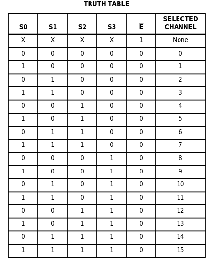
One disadvantage of the tiny WiFi-capable ESP8266 micro-controller is its single analog input pin. This makes it impossible to measure, for instance, multiple photo-resistors at once. To solve this issue we experimented with using a 1-to-16 channel multiplexer known as CD74HC4067. This particular multiplexer let’s you read from 16 different possible analog devices by switching between them. Like all microchips, the idea behind the switch is to use a logic scheme to change between the channels. To control the CD74HC4067 you need to sacrifice 5 of the GPIO pins. Here’s the logic table obtained from the Texas instruments website:
Wiring
Here’s how to wire the ESP8266 to one of these multiplexers:
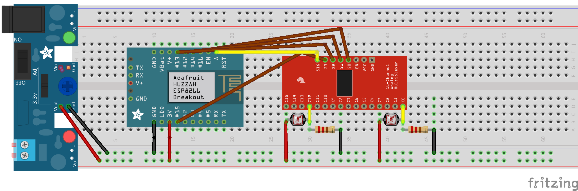
In this example we connected 2 photoresistors to 2 different analog channels (0 and 12).
Micropython for CD74HC4067
We wrote a micropython class for ESP8266 (Huzzah Feather in particular) to be able to easily control and read from the analog channels. Let’s go through it step by step:
We first use micropython’s machine module to control the output from 5 GPIO pins of choice and the single analog input:
import machine

class Mux:
    def __init__(self, S0, S1, S2, S3, E, signal=0):
        self.S0 = machine.Pin(S0, machine.Pin.OUT)
        self.S1 = machine.Pin(S1, machine.Pin.OUT)
        self.S2 = machine.Pin(S2, machine.Pin.OUT)
        self.S3 = machine.Pin(S3, machine.Pin.OUT)
        self.E = machine.Pin(E, machine.Pin.OUT)
        self.signal = machine.ADC(signal)
        self._reset()
        self.current_bits = "0000"
        self.state = False
Now we are capable of controlling the output pins to change the channel according to the logic table. It’s best practice to create a method to reset all the S pins to 0 at first and the E pin to 1 inside the init. We can add a _reset() function like this to do it:
    def _reset(self):
        self.S0.off()
        self.S1.off()
        self.S2.off()
        self.S3.off()
        self.E.off()
Then we can write a function to simply flip the E state on or off to enable/disable the multiplexer when needed:
    def switch_state(self):
        if self.state:
            self.E(0)
            self.state = False
        else:
            self.E(1)
            self.state = True
Now we need a function to map the channel id to bits and vice versa:
    def _bits_to_channel(self, bits):
        return int("0000" + "".join([str(x) for x in "".join(reversed(bits))]), 2)

    def _channel_to_bits(self, channel_id):
        return ''.join(reversed("{:0>{w}}".format(bin(channel_id)[2:], w=4)))
The trick to the bits_to_channel function is to concatenate the 4 logic bits with a filler of 0000 string and convert it to its corresponding 8bit integer value. Ah, another detail is to also flip the 4 bits (for unknown reasons). Of course, this mapping can also written out and hard coded if you don’t mind the looks. For the channel to bits function, we used python’s built in bin function to first obtain the 8bit string for the channel id and then reverse it before returning. A side note: reversing a list by alist[::-1] does not work in micropython.
Now we need to have a function for switching the pins according to the given channel specific 4bit value:
    def _switch_pins_with_bits(self, bits):
        s0, s1, s2, s3 = [int(x) for x in tuple(bits)]
        self.S0(s0)
        self.S1(s1)
        self.S2(s2)
        self.S3(s3)
Lastly, the most important function takes a channel ID and switches the analog input to that:
    def switch_channel(self, channel_id):
        bits = self._channel_to_bits(channel_id)
        self._switch_pins_with_bits(bits)
        self.current_bits = bits
Example usage
After we put this class into the boot.py file, we can transfer it to the esp8266 and reboot the board.
Then we can turn on the REPL to switch channels and read the signal:
mux = Mux(14, 12, 13, 15, 16)       # this is according to the GPIO wiring used.
mux.switch_state()                 # turns on the reading
print(mux.signal.read())            # reads the signal from channel 0 (default channel → “0000”)
mux.switch_channel(12)             # switches to channel 12
print(mux.signal.read())            # reads from channel 12