We spent our vacation hiding away from the cold, tinkering with electronics, and slowly building up our collection of random electronics components and our knowledge of them. This post gets into setting up a Rust-based environment for programming the blue-pill, an insanely cheap STM32 ARM Cortex-M3 development board that we now own four of. There’s also an example of how to control two servos, something we were looking into for a small paint plotter project we’re working on.
Hardware
- a blue pill board (STM32F103C8T6)
- an ST-Link (V2)
- two S3003 servos (used in the example)
Quickstart
We used the very handy blue-pill-quickstart crate. A basic project cycle using just this is as simple as
- clone blue-pill-quickstart and
cdinto it - write your code
- connect the ST-Link to the blue-pill and to your computer (as explained in the crate README)
screen ./openocd.sh
Now here’s where we ran into trouble. openocd kept saying “Warn : UNEXPECTED idcode: 0x2ba01477”. After some fruitless googling, we ended up following the error back to a file in the openocd directory. No idea what we’re doing here but this fixes the problem:
cd /path/to/open-ocd/0.10.0/share/openocd/scripts/target(/usr/local/Cellar/open-ocdin Mac, if youbrew install-ed it)vim stm32f1x.cfg(or whatever floats your boat)- edit line 34 from
set _CPUTAPID 0x1ba01477toset _CPUTAPID 0x2ba01477
And finally, detach the screen and cargo run your code.
Edits
3 March 2020
It turns out the blue-pill-quickstart crate has had some updates recently so the code in this post is slightly out of date. As far as I can tell the only difference is that the way the stm32f1xx-hal crate is referred to is changed, meaning all references to hal in the code need to be replaced with stm32f1xx_hal (from this commit). I didn’t have time to test this yet though so instead here’s our Cargo.toml that works with this code (thanks, Greg Woods, for pointing out that this was missing!):
Cargo.toml
[package]
name = "rust-blue-pill-setup"
version = "0.1.0"
authors = ["ninjani"]
edition = "2018"

[dependencies]
cortex-m = "0.5"
cortex-m-rt = { version = "0.6.6", features = ["device"] }
panic-semihosting = "0.5"

[dependencies.hal]
git = "https://github.com/japaric/stm32f103xx-hal"
branch = "master"
package = "stm32f103xx-hal"
features = ["rt"]
Debugger
The VSCode Cortex-Debug extension is slick, though I prefer IntelliJ for my normal Rust code since VSCode lags like crazy on the slightly larger codebases (looking at you, Rosalind). You install it and, in the Debug tab, configure it to do this:
{
    "version": "0.2.0",
    "configurations": [
	{
	    "name": "Cortex Debug",
	    "cwd": "${workspaceRoot}",
	    "executable": "./target/thumbv7m-none-eabi/debug/${workspaceFolderBasename}",
	    "request": "launch",
	    "type": "cortex-debug",
	    "servertype": "openocd",
	    "device": "STM32F103C8T6",
	    "configFiles": [
		"interface/stlink-v2.cfg",
		"target/stm32f1x.cfg"
	    ],
	}
    ]
}
Add breakpoints in your code, cargo build, and start debugging.
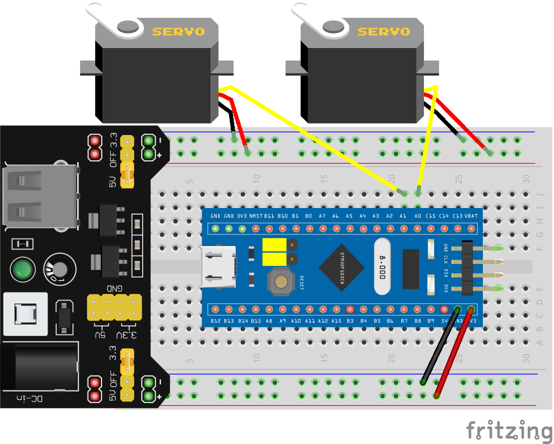
Servos example
This code is something we used for testing two servos together, as part of a controllable painting robot idea that we’re working on. Here’s the wiring (using a breadboard power supply):
#![deny(unsafe_code)]
#![no_std]
#![no_main]

extern crate panic_semihosting;
use core::iter::Iterator;
use cortex_m_rt::entry;
use hal::{delay::Delay, device, prelude::*};

type Pwm = (
    hal::pwm::Pwm<hal::stm32f103xx::TIM2, hal::pwm::C1>,
    hal::pwm::Pwm<hal::stm32f103xx::TIM2, hal::pwm::C2>,
    hal::pwm::Pwm<hal::stm32f103xx::TIM2, hal::pwm::C3>,
    hal::pwm::Pwm<hal::stm32f103xx::TIM2, hal::pwm::C4>,
);

// This needed some experimentation, only works for our wooden arm thing
const MIN_DUTY_DIVIDER: u16 = 45;
const MAX_DUTY_DIVIDER: u16 = 13;

#[inline]
fn get_duty_from_angle(
    angle: u16,
    min_duty: u16,
    max_duty: u16,
    min_angle: u16,
    max_angle: u16,
) -> u16 {
    min_duty + angle * ((max_duty - min_duty) / (max_angle - min_angle))
}

#[entry]
fn main() -> ! {
    // Boilerplate
    let core_peripherals = cortex_m::Peripherals::take().unwrap();
    let device_peripherals = device::Peripherals::take().unwrap();
    let mut flash = device_peripherals.FLASH.constrain();
    let mut rcc = device_peripherals.RCC.constrain();
    let clocks = rcc.cfgr.freeze(&mut flash.acr);
    let mut afio = device_peripherals.AFIO.constrain(&mut rcc.apb2);

    // We're using Timer 2 which uses the GPIOA pins
    // PA0, PA1, PA2, and PA3 (labeled A0, A1 etc. on the blue-pill)
    let mut gpioa = device_peripherals.GPIOA.split(&mut rcc.apb2);
    let (c1, c2, c3, c4) = (
	gpioa.pa0.into_alternate_push_pull(&mut gpioa.crl),
	gpioa.pa1.into_alternate_push_pull(&mut gpioa.crl),
	gpioa.pa2.into_alternate_push_pull(&mut gpioa.crl),
	gpioa.pa3.into_alternate_push_pull(&mut gpioa.crl),
    );
    let mut servos = device_peripherals.TIM2.pwm(
	(c1, c2, c3, c4),
	&mut afio.mapr,
	50.hz(), // The usual hobby servo frequency
	clocks,
	&mut rcc.apb1,
    );
    // You can connect up to four servos on the same timer
    // It's 0 and 1 here since the servos are at A0 and A1
    servos.0.enable();
    servos.1.enable();
    let duty = servos.0.get_max_duty();
    let (min_duty, max_duty) = (duty / MIN_DUTY_DIVIDER, duty / MAX_DUTY_DIVIDER);

    // This is to give it some time to move
    let delay = Delay::new(core_peripherals.SYST, clocks);

    // Spins the two servos in opposite directions
    // 10 degrees at a time, 5 times
    for _ in 0..5 {
	for angle in (0..181).step_by(10) {
	    delay.delay_ms(100u16);
	    servos
		.0
		.set_duty(get_duty_from_angle(angle, max_duty, min_duty, 0, 180));
	    servos
		.1
		.set_duty(get_duty_from_angle(180 - angle, max_duty, min_duty, 0, 180));
	    delay.delay_ms(100u16);
	}
    }
    servos.0.set_duty(0);
    servos.1.set_duty(0);
    loop {}
}